Loading Network
- Start Cytoscape and download the demo network.
- Open the demo network using
File → Open... - When the network first opens, the entire network is not visible because of the default zoom factor used. To see the whole network, we can use the
View → Fit Content function.
Filter Interactions
- Your network contains a combination of protein-protein (pp) and protein-DNA (pd) interactions. Next, we will filter out the protein-protein interactions to focus on the protein-DNA interactions.
- First, let's select all protein-protein interactions.
- Go to the
Select tab in the Cytoscape Control Panel (the leftmost panel). - Click on the
+ and create aColumn Filter . - Click on
Choose column... and select Edge: interaction - Now in the text field enter
pp . This will select all of the edges with the protein-protein interactions. - You should now see many edges in the network selected (i.e., colored red).
- Since we're only interested in the protein-DNA edges, we can delete the protein-protein edges we've just selected.
- To delete selected nodes or edges, you can just hit the DELETE key or use the menu
Edit → Delete Selected Nodes and Edges - You should now see many unconnected nodes in the network.
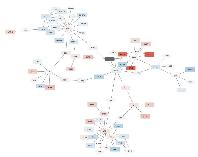
- Now, lets clean up the network by applying a force-directed layout under
Layout → Prefuse Force Directed Layout . - The largest component of the final filtered and cleaned up network should look like this:
Observe the Network
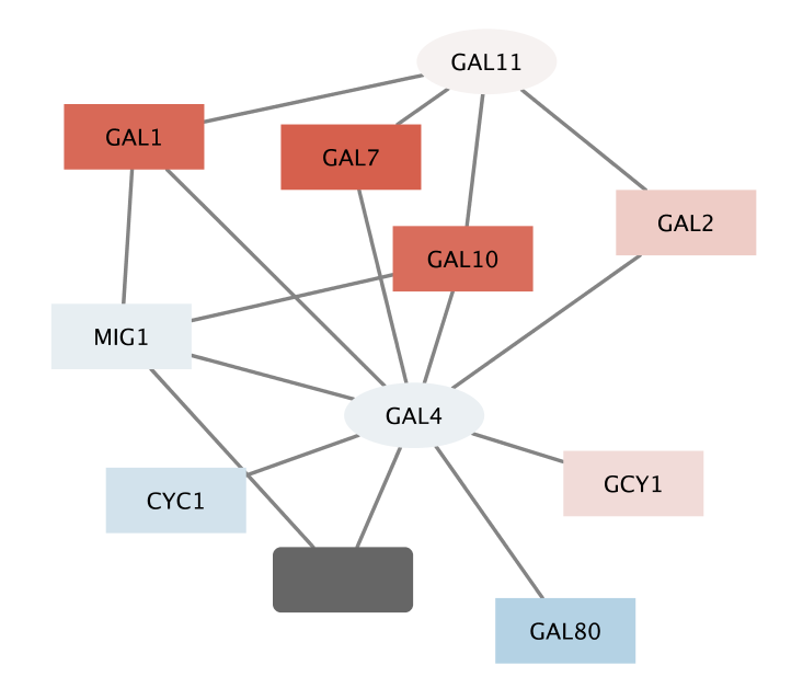
- Notice that three dark red (highly induced) nodes are in the same region of the graph.
- Notice that there are two nodes that interact with all three red nodes: GAL4 (YPL248C) and GAL11 (YOL051W).
- Let's select these two nodes and their immediate neighbors.
- First select GAL4 (YPL248C) by clicking on it.
- Now, extend the selection by holding down the shift key and clicking on GAL11 (YOL051W).
- Finally, select their neighbors by control-6 (or ⌘-6 on a Mac), or by the menu
Select → Nodes → First Neighbors of Selected Nodes → Undirected - It is sometimes useful to create a new network from selected nodes.
- Create a new network by selecting
File → New → Network → Selected nodes, all edges . - (Even though we say all edges, only the edges connecting the selected nodes will actually be used.)
- As before, we may need to do a
View → Fit Content .
With some layout and zooming, this new network should appear similar to the one shown: